Instructions for LED strips, modules, flexible neon
For the correct operation of LED products and in order to avoid malfunctions, it is necessary to adhere to the storage and operation conditions, as well as correctly calculate the power supply and install it. Only if the following rules and recommendations are followed, the long-term operation of the product is guaranteed.
Storage conditions:
Products should be stored in a dry, dark place.
Storage temperature: from -30º C to +60º C at a relative humidity of not more than 70%.
Operating conditions:
Working temperature : from -20º C to +60º C
Operating voltage 12V±5% (Exceeding the operating voltage range may cause malfunctions or damage the product). Working time no more than 16 hours a day.
LED strips without waterproof coating, protection class IP20, are designed for indoor use, with a relative humidity of not more than 70% and outdoors under a canopy that can reliably protect the strip from direct sunlight and liquid drops.
Products with protection class IP65 and above can be used outdoors in an aluminum profile with a diffuser or in a letter (lightbox), avoiding direct contact with water and sunlight.
Power supply calculation:
Before operation, it is necessary to correctly calculate the power consumption of the LEDs When choosing a power source, use the rule that the power of the power supply must be greater than the total power of the connected load and have a margin of 20%.
In order to calculate the power of the power supply (Rip, W), you need to multiply the power consumption of one meter of tape / one module (Pm, W / m) by the number of meters / modules connected to the power supply (L, m), and then multiply all on the safety factor Kz = 1.2
Rip = Pm × L × Kz
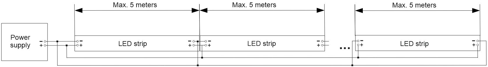
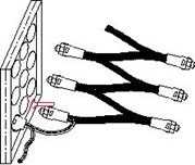
For proper operation, LED strips must be powered no more than 5 meters from one power source. Sections over 5m must be connected to the main power line separately. This will increase the service life and make the glow more uniform. Scheme 1 for connecting a monochrome tape (flexible neon):
Scheme 2 connecting RGB tape:
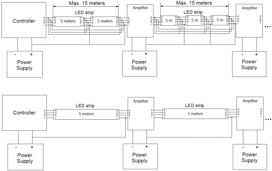
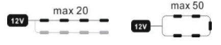
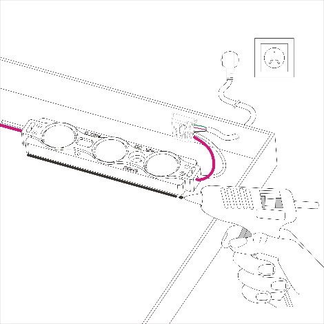
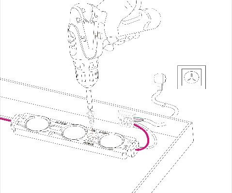
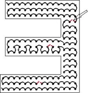
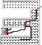
For proper operation of the LED modules, lay the main power wires (lines) and connect to individual LED lines. Make sure that the number of modules connected in one line (in series) does not exceed the recommended (20 pcs.). If this number is exceeded, the modules must be “ringed” (powered from both sides of the circuit). The number of modules in such a chain should not exceed 50 pcs.
Wiring diagram for LED modules
Before turning on the product, make sure that the power supply is connected with the correct polarity.
When installing modules and ribbons
- During installation and operation, it is forbidden to press, hit, scratch, stretch, break or subject the tape / module to other mechanical influences. It is forbidden to leave the tape in the reel for a long time, more than 1 minute.
- Before turning on the assembled structure, it is necessary to check for short circuits and eliminate them. Non-insulated wires must be insulated.
- The diameter of the wire from the power source depends on the type of LED strip, the number of plug-in modules, as well as the distance between the power supply and the LED strip. We do not recommend placing the power supply more than 5 m (five meters) from the product.
The recommended diameters of the copper power wire are shown below.
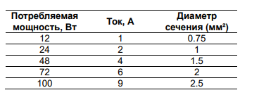
Note: if you need to connecthigher power, then you need to increase the cross section of the wires in proportion to supply current.
4. Do not use AC voltage sources, as well as power supplies whose output voltage does not match the input voltage of the LED strip/module specified in the technical specifications.
5. Before turning on, make sure that the input voltage of the power supply is within its operating range.
6. When handling the ribbon/module, observe ESD regulations. Static electricity can damage LEDs, shortening their lifespan and causing them to fail.
7. Tape/modules are supplied in sealed packages. The consumer must ensure the protection of products from aggressive environments, humidity, and other harmful effects during transportation, storage and installation. Note: Belt corrosion damage is not a manufacturing defect and is not covered by warranty
LED strip installation:
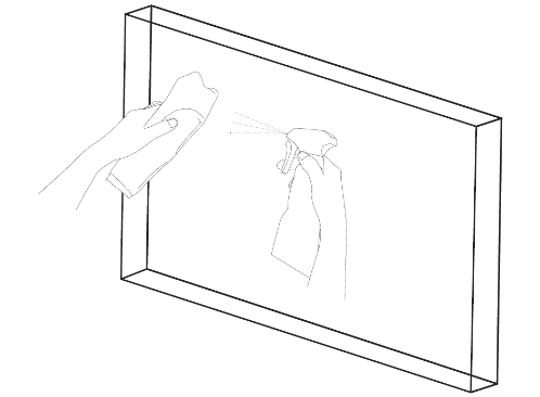
- Clean, degrease and dry the surface where the LED products will be installed
- Remove the protective layer of tape and apply the tape. Gently press the tape against the surface to be mounted until it is firmly bonded (do not put pressure on the LEDs, resistors and controls). The surface to which the tape is to be applied must be solid, without breaks, to avoid damage to the tape. For a tape with a substrate width of 5mm 120d/m, a heat sink must be provided
- Connect the LED strip to the power wire every 5 meters (the diagrams for connecting LED strips are shown above).
- The tape can be cut into segments with a minimum number of LEDs equal to 3 pcs. Each cut line is marked with a black stripe and has two pairs of pads on both sides for further connection.
- Only connect pieces of tape/modules by soldering on the designated areas (they are marked as “+/-” or “+/RGB”). Soldering time should not exceed 10 seconds at 260 degrees.
Installation of LED modules:
1.Clean, degrease and dry the surface where the LEDs will be installed.
2.Remove the protective tape and arrange the modules according to the layout. Perform the switching according to the diagram above.
3. Connect the LEDs to a power source. Check the sign for the quality of illumination (light level, glow shade, illumination uniformity). Then secure the modules with screws or acetone-free glue.
Flexible neon installation:
-
- Prepare the surface on which the flexible neon will be attached. Mounting on
is allowed
– special U-shaped clips included in the kit;
– milled grooves for the size of neon. At the same time, flexible neon should enter the grooves easily, it is forbidden to use force. To fix the flexible neon in the groove, use LOCTITE 454 glue;
– fastening to the surface with LOCTITE 454 glue;
– Sealing of plugs and soldering points should be carried out with LOCTITE 454.
- Connect the flexible neon to the power wire every 5 meters (diagram 1).
- Flexible neon can be cut into segments in places marked with special cut lines. Each cut line is marked with a black stripe and has two pairs of contact pads on both sides for further connection. The ends must be closed with a silicone plug included in the kit, which sits on flexible neon using a sealant.
- Connecting neon segments by soldering should be carried out only on designated sites (they are marked as “+/-”). Soldering time should not exceed 5 seconds at a temperature of 260 degrees. When soldering segments, it is strictly forbidden to use soldering acids and acid fluxes. Soldering points must be sealed against moisture.
Installation and operation of quick-mount diodes:
1. Install the modules in the pre-milled holes.
2. Every 50 pixels should be healed on both sides (ringed)
3. The power source should not be located further than 5 meters.
4. Using LEDs in dynamic mode significantly increases their lifespan.
5. 24-hour operation and use under glass in gas station ceilings are prohibited.
Claims for the quality of the glow after the installation of the sign at the end customer without a preliminary check in the shop are not accepted.